
Choke And Kill Manifolds Components
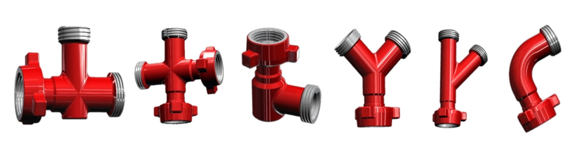
Choke and kill manifold components include swivel joints, integral joints, high-pressure pup joints, and short conversion (adjustable) joints.
All components can be manufactured according to customer specifications
-
◆ Technical Data
◆ Product Description
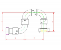
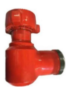
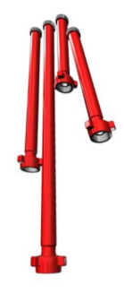
High pressure movable elbow is a kind of metal pipeline joint equipped with ball bearings, which is a common tool for connecting pipelines and washing sand in oilfield workover operations. It has the characteristics of variable adjustment orientation, quick connection, reasonable structure, small volume, light weight, good sealing performance, safety and reliability, and easy operation. Its specifications are 2"~4", rated working pressure 42~105MPa (6000psi~15000psi), can provide a variety of models of normal temperature, low temperature and sulfur gas conditions used in the repair kit
◆ Design Features
● Swivel Joints is bent on CNC machine tools, molding, uniform thickness and long service life.visual quality can be comparable with the import of rough
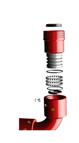
● Synthetic rubber seals with metal ring blowout preventer, while the design of pressure relief hole when the seal leakage is automatically reduced to prevent pressure accumulated in the cavity of the fairway,the use of security is greatly enhanced
● Swivel Joints three fairways designed to more effectively withstand heavy load and radial load,so that when the pressure stable when subjected to changing load, smaller pipeline vibration
● Swivel Joints field service usually requires only occasional lubric-ation can ensure their normal work
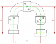
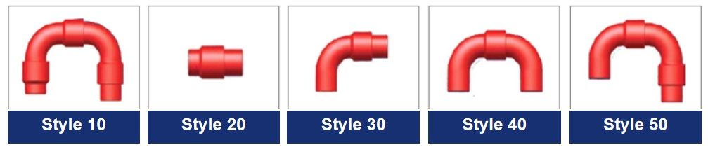
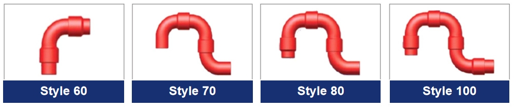
- Long radius bend 10 Swivel Joints
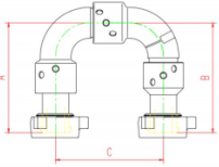
- Long radius bend 50 Swivel Joints
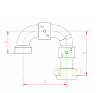
- Long radius bend 80 Swivel Joints
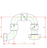
- Long radius bend 100 Swivel Joints
- Active elbow repair kit
-
Product Name
Specification
Working Pressure
Type of Connection
Dimensions
(mm)
Weight
(kg)
Use Conditions
Drawing
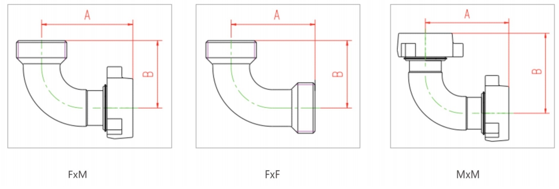
A
B
C
Long Radius Bend Swivel Joints
2"
42/6000
FIG602(F×M)
279
277
273
24.5
standard
Type 10 F-M
3"
FIG602(F×M)
368
368
416
55.3
standard
FIG602(M×M)
368
368
416
61.4
standard
4"
FIG602(M×M)
408
408
484
85.8
standard
2"
70/10000
FIG1002(F×M)
279
277
273
27.7
standard
3"
FIG1002(F×M)
368
368
416
58.7
standard
4"
FG1002(F×M)
408
408
484
89.8
standard
Type 10 M-M
2"
105/15000
FIG1502(F×M)
279
277
273
27.7
standard
FIG1502(M×M)
279
277
273
31.8
standard
3"
FIG1502(M×M)
368
368
416
64.8
standard
FIG1502(F×M)
368
368
416
58.7
standard
4"
FIG1502(F×M)
408
408
484
89.8
standard
-
Product
Name
Specification
Working
Pressure
Type of
Connection
Dimensions
(mm)
Weight
(kg)
Use
Conditions
Drawing
A
B
C
Long Radius Bend Swivel Joints
2"
42/6000
FG602(F×M)
140
277
277
23.4
standard
Type 50 F-M
3"
FIG602(F×M)
202
268
416
45.2
standard
4"
FIG602(F×M)
236
406
481
70.2
standard
2"
70/10000
FG1002(F×M)
140
277
277
25.5
standard
3"
FIG1002(F×M)
202
268
416
48.4
standard
4"
FIG1002(F×M)
236
406
481
125
standard
2"
105/15000
FIG1502(F×M)
140
277
277
25.5
standard
2"
FIG1502(M×M)
140
277
277
27.2
standard
3"
FIG1502(M×M)
202
268
416
52.3
standard
3"
FG1502(F×M)
202
268
416
48.4
standard
4"
FIG1502(F×M)
236
406
481
73.3
standard
-
Product
Name
Specification
Working Pressure
Type of
Connection
Dimensions
(mm)
Weight
(kg)
Use
Conditions
Drawing
A
B
C
D
Long Radius Bend Swivel Joints
2"
42/6000
FIG602(F×M)
277
277
273
140
34.2
standard
Type 80 F-M
3"
FG602(F×M)
416
368
416
202
62.1
standard
4"
FIG602(F×M)
406
406
408
236
80.5
standard
2"
70/10000
FIG1002(F×M)
277
277
273
140
36.5
standard
3"
FIG1002(F×M)
416
368
416
202
65.9
standard
4"
FIG1002(F×M)
406
406
408
236
85.3
standard
2"
FIG1502(F×M)
277
277
273
140
36.5
standard
3"
FIG1502(FxF)
416
368
416
202
65.9
standard
4"
FIG1502(F×M)
406
406
408
236
85.3
standard
-
Product
Name
Specification
Working Pressure
Type of
Connection
Dimensions
(mm)
Weight
(kg)
Use
Conditions
Drawing
A
B
C
D
Long Radius Bend Swivel Joints
2"
42/6000
FIG602(F×M)
273
277
273
279
33.7
standard
Type 100 F- M
3"
FIG602(F×M)
416
368
416
368
74.3
standard
4"
FIG602(F×M)
408
406
408
327.5
94.8
standard
2"
70/10000
FIG1002(F*M)
273
277
273
279
37.5
standard
3"
FIG1002(F*M)
416
368
416
368
76.1
standard
4"
FIG1002(F*M)
408
406
408
327.5
98.5
standard
2"
105/15000
FIG1502(F*M)
273
277
273
279
37.5
standard
2"
FIG1502(M*M)
273
277
273
279
40.7
standard
3"
FIG1502(M*F)
416
368
416
368
76.1
standard
-
Product
Name
Specification
Working Pressure
Packing
(A only)
O-ring
Steel Ball Stopper
Circlip For Hole
Oil Plug
Steel Ball
Drawing
I
Ⅱ
Ⅲ
Repair Kit
2"
42/6000
1
1
1
3
3
3
3
28
3"
1
1
1
3
3
3
3
38
4"
1
1
1
3
3
3
3
45
2”
70/10000
1
1
1
3
3
3
3
28
3"
1
1
1
3
3
3
3
38
4"
1
1
1
3
3
3
3
45
2"
105/15000
1
1
1
3
3
3
3
28
2"
1
1
1
3
3
3
3
28
3"
1
1
1
3
3
3
3
38
4"
1
1
1
3
3
3
3
45
-
◆ Technical Data
◆ Product Description
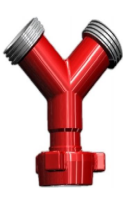
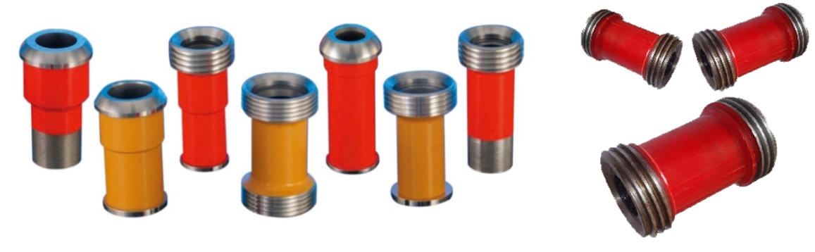
The integral joint is an indispensable part in the connection of high-pressure fluid pipelines, which can effectively realize the functions of fluid diversion, parallel flow, fluid change, etc. The integral joint is a series of products innovated and improved by the company on the basis of digesting and absorbing similar foreign product technology. Its specifications are 2 "~3", rated working pressure 42~105MPa(6000psi~15000psi),it can provide various models and specifications for use under normal temperature, low temperature and sulfur-containing gas conditions. The whole joint variety is complete, the quality is stable, in addition to the types listed below, can be customized according to the user needs for special purposes and specifications of the whole joint.
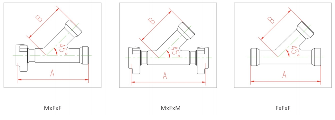
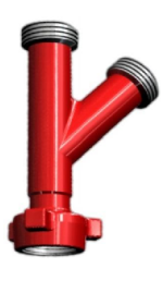
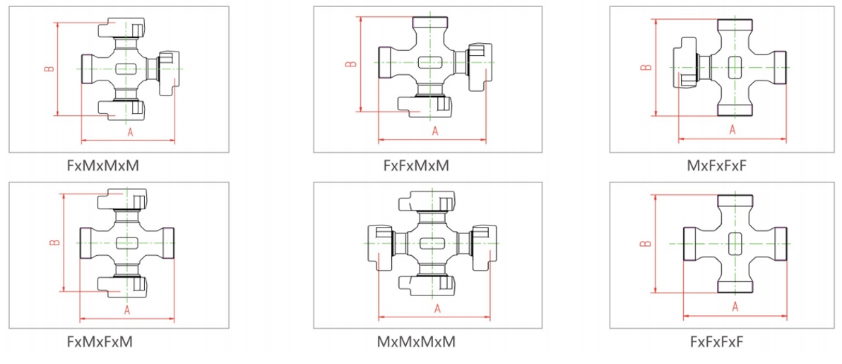
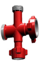
Integral joints (L-shaped 90° elbow, long radius 90° elbow, T-shaped joint, Y-shaped joint, manifold joint, cross joint, etc.)
◆ Design Features
The integral joint is made of high quality alloy steel. After strict heat treatment, it has the characteristics of compact structure, uniform wall thickness, long service life, beautiful appearance, strong interchangeability and convenient connection. In the elbow, joint and other fluid change direction, the inner wall erosion is more serious place designed to do thickening treatment, extend the safe service life
-
Product
NameSpecification
Working
PressureDimensions
(mm)
Type of Connection
Weight
(kg)
Use Conditions
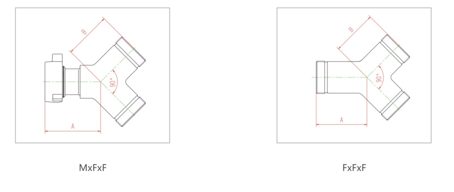
A
B
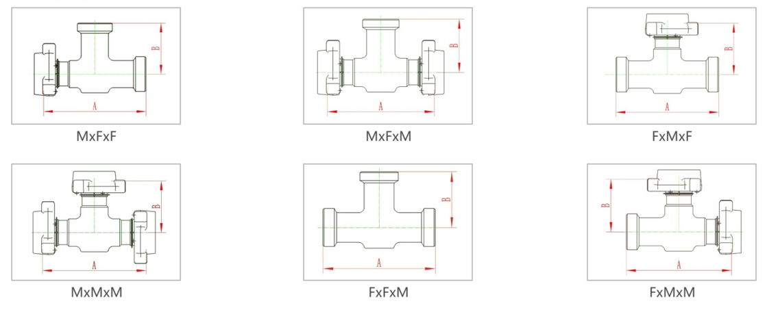
T-Joint2"
42MPa
308
154
FIG602(M×F×F)
14.2
Standard
308
154
FIG602(M×F×M)
16.3
308
154
FIG602(F×M×F)
14.2
308
154
FIG602(F×F×F)
12
308
154
FIG602(M×M×M)
18.6
308
154
FIG602(F×M×M)
16.3
3"
428
214
FIG602(M×F×F)
56.2
428
214
FIG602(M×F×M)
61.7
428
214
FIG602(F×M×F)
56.2
428
214
FIG602(F×F×F)
50.8
428
214
FIG602(M×M×M)
67.1
428
214
FIG602(F×M×M)
61.7
2"
70MPa
308
154
FIG1002(M×F×F)
17
308
154
FIG1002(M×F×M)
20.9
308
154
FIG1002(F×M×F)
17
308
154
FIG1002(F×F×F)
13.2
308
154
FIG1002(M×M×M)
24.7
3"
428
214
FIG1002(F×M×M)
64.4
428
214
FIG1002(M×F×F)
58
428
214
FIG1002(M×F×M)
64.4
428
214
FIG1002(F×M×F)
58
428
214
FIG1002(F×F×F)
51.7
2"
105MPa
308
154
FIG1502(M×F×F)
17
308
154
FIG1502(M×F×M)
20.9
308
154
FIG1502(F×M×F)
17
308
154
FIG1502(F×F×F)
13.2
308
154
FIG1502(M×M×M)
24.7
3"
428
214
FIG1502(F×M×M)
64.4
428
214
FIG1502(M×F×F)
58
428
214
FIG1502(M×F×M)
64.4
428
214
FIG1502(F×M×F)
58
428
214
FIG1502(F×F×F)
51.7
-
Product
NameSpecification
Working
Pressure
Dimensions(mm)
Type of Connection
Weight
(kg)
Use Conditions
A
B
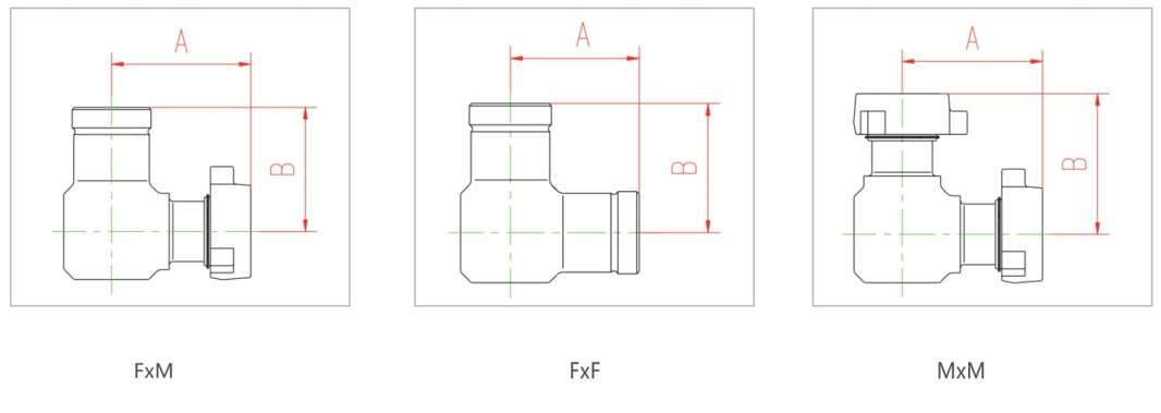
L-90°Elbow2"
42MPa
154
154
FIG602(F×M)
12.4
Standard
154
154
FIG602(F×F)
8.2
154
154
FIG602(M×M)
16.3
3"
214
214
FIG602(F×M)
45.6
214
214
FIG602(F×F)
38.1
214
214
FIG602(M×M)
52.2
2"
70MPa
154
154
FIG1002(F×M)
14.7
154
154
FIG1002(F×F)
10.9
154
154
FIG1002(M×M)
18.5
3”
214
214
FIG1002(F×M)
46.3
214
214
FIG1002(F×F)
39.5
214
214
FIG1002(M×M)
54.9
2"
105MPa
154
154
FIG1502(F×M)
14.7
154
154
FIG1502(F×F)
10.9
154
154
FIG1502(M×M)
18.5
3"
214
214
FIG1502(F×M)
46.3
214
214
FIG1502(F×F)
39.5
214
214
FIG1502(M×M)
54.9
-
Product
Name
Specification
Working
Pressure
Dimensions(mm)
Type of Connection
Weight
(kg)
Use
Conditions
A
B
Long Radius
90 °Elbow2"
42MPa
162
171
FIG602(F×M)
10
Standard

162
171
FIG602(F×F)
7.8
162
171
FIG602(M×M)
12.2
3"
239
202
FIG602(F×M)
24.5
239
202
FIG602(F×F)
19.5
239
202
FIG602(M×M)
29.5
2"
70MPa
162
171
FIG1002(F×M)
12.6
162
171
FIG1002(F×F)
11.8
162
171
FIG1002(M×M)
15.4
3"
239
202
FIG1002(F×M)
22.9
239
202
FIG1002(F×F)
15.8
239
202
FIG1002(M×M)
30
2"
105MPa
162
171
FIG1502(F×M)
12.6
162
171
FIG1502(F×F)
11.8
162
171
FIG1502(M×M)
15.4
3"
239
202
FIG1502(F×M)
22.9
239
202
FIG1502(F×F)
15.8
239
202
FIG1502(M×M)
30
-
Product
NameSpecification
Working
Pressure
Dimensions(mm)
Type of ConnectionWeight
(kg)
Use ConditionsA
B
Y-Type Joint
2"
42MPa
133
127
FIG602(M×F×F)
12.2
Standard
133
127
FIG602(F×F×F)
10
3"
197
190
FIG602(M×F×F)
33.5
197
190
FIG602(F×F×F)
28.5
2"
70MPa
133
127
FIG1002(M×F×F)
12.7
133
127
FIG1002(F×F×F)
10.5
3"
197
190
FIG1002(M×F×F)
35.2
197
190
FIG1002(F×F×F)
30.5
2"
105MPa
133
127
FIG1502(M×F×F)
12.7
133
127
FIG1502(F×F×F)
10.5
3"
197
190
FIG1502(M×F×F)
35.2
197
190
FIG1502(F×F×F)
30.5
-
Product
NameSpecification
Working
PressureDimensions
(mm)
Type of Connection
Weight
(kg)
Use
Conditions
A
B
Manifold Joint
2"
42MPa
400
250
FIG602(M×F×F)
21.5
Standard
400
250
FIG602(M×F×M)
23.7
400
250
FIG602(F×F×F)
19.3
3"
533
355
FIG602(M×F×F)
40.1
533
355
FIG602(M×F×M)
45.1
533
355
FIG602(F×F×F)
35.1
2"
70MPa
400
250
FG1002(M×F×F)
24.5
400
250
FIG1002(M×F×M)
26.7
400
250
FIG1002(F×F×F)
22.3
3"
533
355
FIG1002(M×F×F)
43.1
533
355
FIG1002(M×F×M)
48.1
533
355
FIG1002(F×F×F)
38.1
2"
105MPa
400
250
FIG1002(M×F×F)
24.5
400
250
FIG1002(M×F×M)
26.7
400
250
FIG1002(F×F×F)
22.3
3"
533
355
FIG1002(M×F×F)
43.1
533
355
FIG1002(M×F×M)
48.1
533
355
FIG1002(F×F×F)
38.1
-
Product
NameSpecification
Working
PressureDimensions
(mm)
Type of Connection
Weight
(kg)
Use Conditions
A
B
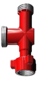
Crosses Joint
2"
42MPa
308
308
FIG602(F×M×M×M)
32.7
Standard
308
308
FIG602(F×F×M×M)
30.4
308
308
FIG602(M×F×F×F)
28.1
308
308
FIG602(F×M×F×M)
30.4
308
308
FIG602(M×M×M×M)
35
308
308
FIG602(F×F×F×F)
26.3
3"
428
428
FIG602(F×M×M×M)
87.1
428
428
FIG602(F×F×M×M)
81.6
428
428
FIG602(M×F×F×F)
76.2
428
428
FIG602(F×M×F×M)
81.6
2"
70MPa
308
308
FIG1002(F×M×M×M)
36.3
308
308
FIG1002(F×F×M×M)
33.1
308
308
FIG1002(M×F×F×F)
30
308
308
FIG1002(F×M×F×M)
33.1
308
308
FIG1002(M×M×M×M)
39.5
3"
428
428
FIG1002(F×M×M×M)
89.4
428
428
FIG1002(F×F×M×M)
83
428
428
FIG1002(M×F×F×F)
80.7
428
428
FIG1002(F×M×F×M)
83
2"
105MPa
308
308
FIG1502(F×M×M×M)
36.3
308
308
FIG1502(F×F×M×M)
33.1
308
308
FIG1502(M×F×F×F)
30
308
308
FIG1502(F×M×F×M)
33.1
308
308
FIG1502(F×F×F×F)
26.8
3"
428
428
FIG1502(F×M×M×M)
89.4
428
428
FIG1502(F×F×M×M)
83
428
428
FIG1502(M×F×F×F)
80.7
428
428
FIG1502(F×M×F×M)
83
-
-
◆ Product Description Description
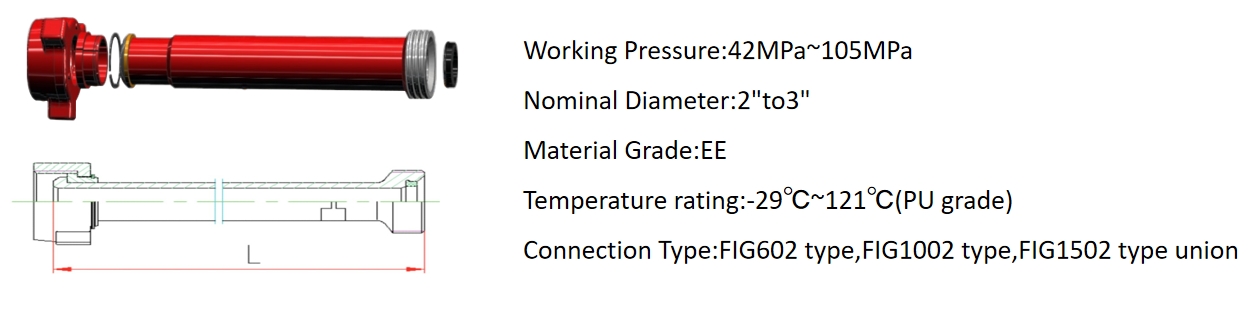
Pup joint is an element cementingand fracturing equipment delivery high-pressure fluid.Widely usedin the acidic operating environment.in the high-pressure discharge line,input line,a temporary flow lines,well testing,and other high-voltage transmission line on the line.Overall pipeline specifications are 2in~3 in,length 0.5 m,1 m,1.5 m,2m,2.5m,3m,3.5m and so on,rated working pressure of 42MPa 105MPa,working temperature -29 ℃~121℃.We can Produce reduction according to customer requirement.Pup joint is an element cementing and fracturing equipment delivery high-pressure fluid. Widely used in the acidic operating environment.in the high-pressure discharge line,input line,a temporary flow lines,well testing,and other high-voltage transmission line on the line.Overall pipeline specifications are 2in~3 in,length 0.5 m,1 m,1.5 m,2m,2.5m,3m,3.5m and so on,rated working pressure of 42MPa~105MPa,working temperature -29℃~121℃.We can Produce reduction according to customer requirement.
◆ Design Features
● Pup jointend on the grounds azelaic without screwing, more secure and reliable
● Loading and unloading easy, fast
● High strength, lightweight
● Various technical parameters and performance meetthe specifications of API Spec 16C, interchangeable with similar foreign products
◆ Technical Data
Product Name
Specification
Working Pressure
Length
( mm )
Type of ConnectionWeight
(kg)
Use
Conditions
L
2"
3"
High-
Pressure Pup Joint2"
3"42MPa
500
FIG602(F×M)
FIG602(F×F)
FIG602(M×M)8.8
18.7
Standard
1000
15
32.4
1500
21.4
46.1
2000
27.8
59.8
2500
34.2
73.5
3000
40.6
87.2
4000
53.4
114.6
5000
66.2
142
6000
79
170
2"
3"70MPa
500
FIG1002(F×M)
FIG1002(F×F)
FIG1002(M×M)8.8
18.7
1000
15
32.4
1500
21.4
46.1
2000
27.8
59.8
2500
34.2
73.5
3000
40.6
87.2
4000
53.4
114.6
5000
66.2
142
6000
79
170
2"
3"105MPa
500
FIG1502(F×M)
FIG1502(F×F)
FIG1502(M×M)8.8
18.7
1000
15
32.4
1500
21.4
46.1
2000
27.8
59.8
2500
34.2
73.5
3000
40.6
87.2
4000
53.4
114.6
5000
66.2
142
6000
79
170
-
◆ Product Description
Adjustable joints at both ends is a different size,buckle-type fittings,tubing connections are essential parts can be manufactured according to user needs.Its specifications are 2"to 4",has rated working pressure 42MPa (6000PSI)and 70MPa(15000PSI),an interface in the form of a variety of types including domestic thread,union class.Available at room temperature,low temperature and sour gas conditions.
◆ Design Features
Our factory plant a variety of end connections form, size of adjustable joints, adjustable joints standard total length of 200mm. Users can according to their needs,the following lit of optional end connection in the form of arbitrary combination and non-standard length.Rated working pressure reducers by connecting the end fitting in the form of lower pressure rating value is determined
◆ Technical Data
No.
End Connections
Rated Working Pressure
Standard Conditions
H₂S Conditions
1
2"FIG602F
42MPa
42MPa
2
2"FIG602M
42MPa
42MPa
3
2"FIG1502F
105MPa
70MPa
4
2"FIG1502M
105MPa
70MPa
5
3"FIG602F
42MPa
42MPa
6
3"FIG602M
42MPa
42MPa
7
3"FIG1502F
105MPa
70MPa
8
3"FIG1502M
105MPa
70MPa
9
4"FIG602F
42MPa
42MPa
10
4"FIG602M
42MPa
42MPa
11
4"FIG1502F
105MPa
70MPa
12
4"FIG1502M
105MPa
70MPa
NOTE:Thread contained pipe threaded,can be customized according to customer demand


OUR PRODUCTS
Anhui MK Petroleum Precision Manufacturing Co. , Ltd.
MKmfg main products: flange,choke manifolds, kill manifolds,hose loop,swivel joints, integral joints, high-pressure pup joints and short conversion (adjustable) joint ... etc.
If you are interested in any of our products, please feel free to contact us.
QUICK ACCESS
OUR COMPANY